5 BREADBOARD PROJECTS FOR BEGINNERS


• 1x UM66 ic
• 1x bc547
• 1x 1K resistor
• 1x 8 ohm speaker
• 2x AA or AAA batteries
• 1x Battery holder


Here are the parts required for all the mentioned projects. Some of them can be removed if you don't want to attempt all the projects. The total cost of all the parts is around $5 or 300 INR which varies according to the store of website you buy the parts from.If you live in mumbai then you may buy it from lamington ;)
STEP1:PARTS:
1) ICs:
• 1x UM66
• 1x 555 timer
• 1x 4026
• 1x 4060
2) Transistors:
• 3x bc547 or 2n2222 or 2n3904
• 1x bc557
3) Resistors:
• 1x 220 ohm
• 1x 33K
• 1x 47K
• 2x 1M
• 1x 100K
• 1x 4.7K
• 1x 680 ohm
• 1x 470 ohm
• 1x 2.2K
• 2x 1K
4) Capacitors:
1) ICs:
• 1x UM66
• 1x 555 timer
• 1x 4026
• 1x 4060
2) Transistors:
• 3x bc547 or 2n2222 or 2n3904
• 1x bc557
3) Resistors:
• 1x 220 ohm
• 1x 33K
• 1x 47K
• 2x 1M
• 1x 100K
• 1x 4.7K
• 1x 680 ohm
• 1x 470 ohm
• 1x 2.2K
• 2x 1K
4) Capacitors:
• 2x 10uf (electrolytic)
• 1x 100uf (electrolytic)
• 1x 100nf (non- electrolytic)
• 1x 10nf (non- electrolytic)
• 2x 1nf (non- electrolytic)
5) Miscellaneous:
• 2x 1.5v AA or AAA batteries
• 1x Battery holder
• 1x 9v battery
• 1x 9v battery holder
• 1x Toggle switch
• 1x 8 ohm speaker
• 1x IR receiver (TSOP)
• 6x LEDs
• 1x LDR
• 2x 1n4148 or 1n4001 diodes
• 1x 50K or 47K potentiometer
• 1x Momentary push button
• 1x 7 segment display
• 1x Breadboard
• Hookup or jumper wire
TOOLS:
- Wire cutter/stripper
- Pliers
- Breadboard power supply
STEP 2:KNOW YOUR BREADBOARD.
A breadboard is a construction base for prototyping of electronics. Originally it was literally a bread board, a polished piece of wood used for slicing bread. In the 1970s the solderless breadboard (AKA plugboard, a terminal array board) became available and nowadays the term "breadboard" is commonly used to refer to these. "Breadboard" is also a synonym for "prototype".
Because the solderless breadboard does not require soldering, it is reusable. This makes it easy to use for creating temporary prototypes and experimenting with circuit design. For this reason, solderless breadboards are also extremely popular with students and in technological education. Older breadboard types did not have this property. A stripboard (veroboard) and similar prototyping printed circuit boards, which are used to build semi-permanent soldered prototypes or one-offs, cannot easily be reused. A variety of electronic systems may be prototyped by using breadboards, from small analog and digital circuits to complete central processing units (CPUs).
Remember the top rows and bottom to rows are veryically shorted.The middle one's are vertically shorted.Please refer to the diagram.
STEP 3:MAKE A PERMENANT POWER SUPPLY THROUGHT THE PROJECT
The black wire connection is for ground and redone is for +vcc(supply)
STEP 4: MAKE A SIMPLE LED CIRCUIT


Make the connection as per the circuit.And remember the shorter leg of led is cathode and longer one is anode.
Always use a resistor in led circuitary,if you don't then the led will blow up :(
so in our case we use 1k resister across led and supply.
STEP 5: PROJECT NO-1 MUSICAL BELL


Parts List:
• 1x UM66 ic
• 1x bc547
• 1x 1K resistor
• 1x 8 ohm speaker
• 2x AA or AAA batteries
• 1x Battery holder
This project can be easily done in 5minutes.The ic UM66 is a melody ic.It has abuilt in oscillator and amplifer which can drive a buzzer.
NOTE:Do not exceed power supply more than 5volts.So you can use 2 AA battries.
STEP 6: PROJECT 2-IR REMOTE TESTER
UUmmm a remote tester...haa..I hope you all find this one more intresting.
so lets get started......
Parts List:
• 1x IR receiver (TSOP)
• 1x bc557 transistor
• 1x 10uf capacitor
• 1x 1K resistor
• 1x 220 ohm resistor
• 1x LED
• 1x IR receiver (TSOP)
• 1x bc557 transistor
• 1x 10uf capacitor
• 1x 1K resistor
• 1x 220 ohm resistor
• 1x LED


NOTE:Use a 6v battery instead of 9v,as TSOP can handle only 6v.If you use 9v then you may damage your TSOP ;(
STEP 7:PROJECT 3-THE FADING LED
As the name already tells, this project fades an led high and low. This is done through the capacitor that is added on pin 3 which repeatedly charges and discharges producing a fading effect which is quite pleasing to see than to think.
SO LETS GET STARTED.......;)
Parts List:
- 1x 555 timer ic
- 1x bc547 transistor
- 1x 33K resistor
- 1x 220 ohm resistor
- 1x 100uf capacitor
- 1x LED
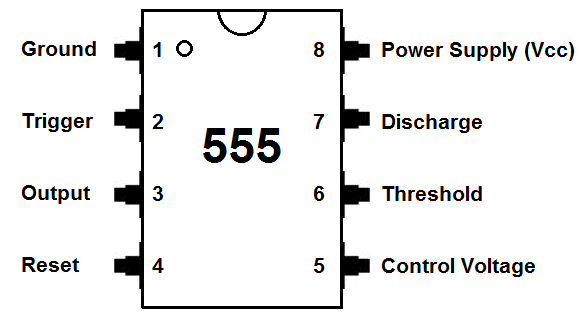
Description:The 555 timer IC is an integrated circuit (chip) used in a variety of timer, pulse generation, and oscillator applications. The 555 can be used to provide time delays, as an oscillator, and as a flip-flop element. Derivatives provide up to four timing circuits in one package.
NOTE:Use a 470 ohm instead of 220 ohm connected to the LED for better results.
STEP 8:PROJECT 4-KNIGHT RIDER
This project is one of my favourite,as by using this I have made a LED HEART CHASER for my nephew.I will provide you that video demonstration down the project.
You can even make a name plate of your own by using this circuitry.
SO LET'S GET STARTED.....
Parts List:
- 1x 555 timer ic
- 1xCD4017 ic
- 1x0.1uf capacitor
- 1x2.2uf capacitor
- 1x1k resistor
- 1x33k resistor
- 1x47k potentiometer(pot)
- 10leds


DESCRIPTION:4017 is a CMOS decade counter cum decoder circuit which can work out of the box for most of our low range counting applications. It can count from zero to ten and its outputs are decoded. This saves a lot of board space and time required to build our circuits when our application demands using a counter followed by a decoder IC.This IC also simplifies the design and makes debugging easy.
In this circuit the output of the 555timer ic goes to the clock of the 4017ic due to which pulse is generated at the pins 3,2,4,7,10,1,5,6,9,11 respectively.
The 47k resistor is use to control the speed of the led
NOTE:Connect the 10 leds carefully as shown in the diagram.
GOTO THIS LINK TO SEE HOW THE LED HEART CHASER WILL LOOK: https://www.youtube.com/watch?v=_v3wi-c2cxc
GOTO THIS LINK TO SEE HOW THE NAME PLATE LOOKS LIKE: https://www.youtube.com/watch?v=St72-txslzE
STEP 9:PROJECT 5-DARK ACTIVATED LED
In this project you will learn how does a led glow automatically in darkness.
In this project we use a LDR(Light Dependent Resistance) which detects the darkness and make led glow ;) .I thing its really cool to do that....
SO LET'S GET STARTED..............
Parts List:
- 1x 555 timer ic
- 1x 10K resistor
- 1x 100K resistor
- 1x 220 ohm resistor
- 1x 100nf capacitor
- 1x 10nf capacitor
- 1x LDR
- 1x LED


DESCRIPTION:The 555 timer is triggered when ldr receives low light making the output high and switching on the led while when more light is detected, the output becomes low switching off the led. This type of circuit is used in automatic street lights that switch on automatically when it turns dark.
LDR: A photoresistor or light-dependent resistor (LDR) or photocell is a light-controlled variable resistor. The resistance of a photoresistor decreases with increasing incident light intensity; in other words, it exhibits photoconductivity.
That's the end of this cool project session. Hope you liked it. I had no idea about the response of people to this post. I assure you if it will be good, I would make another post on it. If you think it was good, then do comment and share this post and do post your pictures if you have made them. Do not forget to comment or ask any questions if you have any doubt. And stay tuned for my next cool posts on electronics ;)
Thanks for watching :)
Bubye...take care and all the very best to all.
No comments:
Post a Comment